

Selection of Linear Transfer Manipulators for Multi‑Press Tandem Lines‑A Guide to Planning Multi‑Press Stamping Production Lines
Share to : 


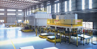
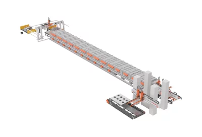
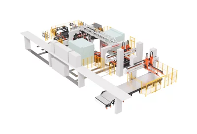
Many factories planning to build a multi‑press tandem stamping line have no clear idea how to select the right linear transfer manipulators. If they are not careful, the chosen equipment may not fit their own production line, operate awkwardly, and be difficult to adjust later. In fact, by sorting out a few core points and planning ahead, you can select a solution that is perfectly matched to your needs, making the subsequent line operation far more effective.
The first step before selection is to thoroughly understand your own operating conditions. Never jump straight to equipment specifications without considering your actual shop‑floor situation—choosing equipment in isolation from real‑world scenarios will inevitably cause problems. Begin by compiling complete data on all the workpieces you produce: the heaviest part weight, the total weight including fixtures, the maximum length and width dimensions, and the materials you typically process (ordinary carbon steel, high‑strength steel, or aluminum). These figures are the foundation for selection. Next, survey the layout of your existing presses: the center‑to‑center distance between each press, the height from the press bed to the floor, and the available die‑open height after the die is opened. These on‑site dimensional data directly determine the required travel ranges of the linear transfer manipulators and whether they can smoothly reach into each press die for loading and unloading. Getting this basic information accurately is a prerequisite for selecting the right equipment.
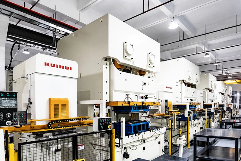
Next, pay close attention to the load margin of the manipulators. Many people tend to choose a rated load that just matches the total weight of the workpiece plus the fixture—this is a misconception. During high‑speed operation, the inertial force of the moving part is significantly greater than its static weight. If the load capacity is too tight, prolonged high‑speed running will likely cause vibration or even part dropping. It is best to add a safety margin of 20% to 50% over the total calculated load. In this way, even if you switch to heavier new workpieces later, the equipment can still handle them without requiring modifications, and its service life will be extended considerably. This is especially true for large automotive body panels—their large size creates greater air resistance and inertia at high speeds, so a generous load margin is essential to maintain long‑term high‑speed stability.
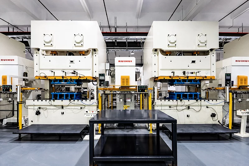
Then, verify the suitability of travel and motion accuracy. The forward/backward stroke of the manipulator must fully cover the entire path from picking a part from one press die to placing it into the next. Do not choose a stroke that just barely meets the requirement; leave adequate clearance to avoid interference between the manipulator and the press during die opening and closing. The vertical stroke also matters—when lowering the part into the die, the manipulator must reach the exact position; when lifting the part away, the bottom of the part must clear the highest point of the die without scraping the die edge. For accuracy, do not rely solely on no‑load theoretical values provided by the manufacturer; always verify the measured repeatability under actual load, ensuring that the placement position is accurate even when carrying a workpiece, so that misalignment does not cause defective stampings.
After that, consider your capacity requirements and confirm whether the manipulator's operating speed can match your needs. If you typically handle large‑batch, fixed‑variety orders, focus on the manipulator's maximum motion speed and check whether it can meet the line's cycle time requirements to achieve full throughput. If you plan to digitize your factory in the future, confirm in advance whether the control system has standard communication ports for direct connection to your MES system without additional hardware modifications. Finally, verify the supplier's local service capability—whether they have nearby service centers and spare parts inventory. In case of minor issues during operation, they should be able to respond quickly to avoid prolonged line downtime caused by small faults.
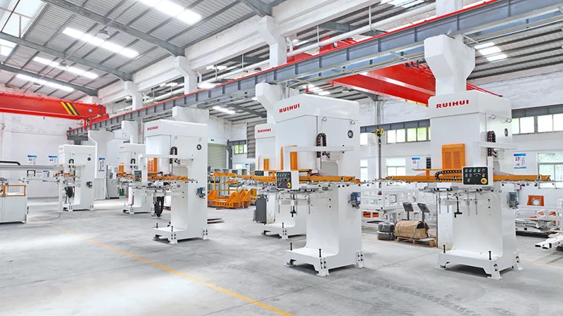
Guangdong RuiHui Intelligent Technology Co., Ltd. employs over 400 staff and has supplied equipment and solutions for nearly 5,000 stamping automation lines. RuiHui has extensive practical experience in the selection of linear transfer manipulators for multi‑press tandem lines and line planning, offering customized solutions that fit each customer's site conditions and actual needs. Many customers in the automotive sheet metal sector have reported excellent matching after RuiHui's planning and implementation, with virtually no incompatibility issues.
By following this guide step by step, you will avoid common pitfalls in selecting linear transfer manipulators for multi‑press tandem lines. The chosen equipment will perfectly fit your production environment, and once the line is commissioned, it will maintain stable and efficient operation, delivering tangible benefits to your production.
With years of hands-on experience, I have honed my skills in navigating the complexities of global commerce, offering invaluable insights and solutions to address customer needs. My commitment to excellence and dedication to customer satisfaction ensure that I deliver exceptional service, guiding clients through every step of the trading process with confidence and proficiency.
You may also like
Related News
Latest Update